Analysis Summary
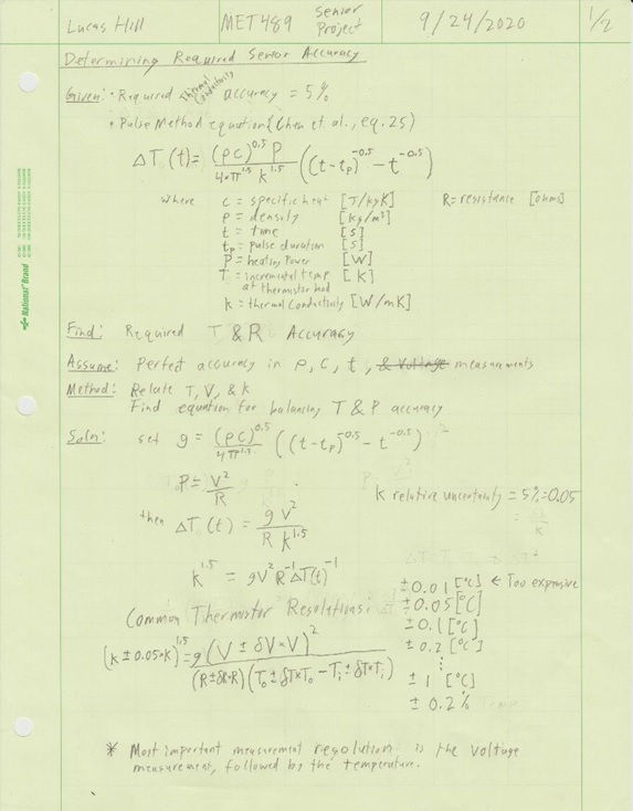
To create TCoMS with the required accuracy of 5% for the thermal conductivity measurements, the voltage measurements over a Wheatstone bridge must also meet a certain accuracy. Using the equation for determining thermal conductivity from a pulse decay style measurement system results in a voltage accuracy requirement of 3.7%. Comparing this value with that of the accuracy of various Arduino boards, it was determined that all of the common boards would work for this system. Using a decision matrix comparing values such as cost and accuracy, it was determined that the Arduino Due is the best option for this project.
Design Requirements
These values were provided as requirements for the thermal conductivity sensor project
Weight: Total must not exceed 20 pounds.
Dimensions: System must fit within an 18[in] x 13[in] x 10[in] box.
Measurement Time: With a max preparation time of 45 minutes, the measured report of thermal conductivity must take less than 15 minutes to complete.
Accuracy: Measured results of testing materials must be within 5% of reference values.
Individual Analyses
Brief summaries of analyses performed for this project are shown below. To see a more details, see the Design & Analysis section of the engineering report.
Analysis 1 - Voltage Resolution Analysis
The 5% measurement accuracy for this project is for the final thermal conductivity value. As this value is found from the voltage, a different accuracy for voltage had to be determined and found to be reachable. The voltage accuracy was determined to be 3.5%. The Arduino Due has a voltage resolution of 0.81 [mV] which was confirmed to be sufficient for TCoMS. The actual choice of board was made using the below decision matrix.
Arduino Board Decision Matrix

Analysis 2 - Stress Analysis of Poker/Probe Rods
To insert the thermistor bead into the testing material, a hole must first be made. This necessitated the design of a part to poke the hole as thermistor beads can't withstand much force. As the same material will be used for both the poker and the probe, minimum material properties needed to be determined. As an assumption based off the maximum device weight, the rods need to withstand 20 pounds of force being directly applied in situations that would cause the largest shear and compression values. The resulting material properties were determined to be 57.2 [MPa] of shear strength and 28.6 [MPa] of compressive strength.
Analysis 3 - Battery Holder Analysis
TCoMS will be powered by a 9 [V] Duracell battery. A part holding the battery to the housing needed to be designed. To ensure that the battery would not cause the part to fail, the stresses in it were found from the battery weight and had a safety factor of 3 applied. For the 3D printing material this resulted in the battery holder needing a 0.12 [mm] shell. A 1 [mm] shell was used for ease of printing.
Analysis 4 - Testing circuitry analysis
To obtain the 5% measurement accuracy, a Wheatstone bridge needed to be design along with a separate heating circuit to generate the heat pulse.
Analysis 5 - Power Source analysis
The Arduino Due requires a voltage supply of between 7 and 12 [V] to operate. As a standard 9 [V] battery meets this requirement it was selected to be the power source. Using the data sheet for the MN 1604 9[V] Duracell Coppertop battery, it is expected that TCoMS will last for approximately 7 hours of continuous operation. As the testing lasts on the order of minutes, 1 of these batteries will be sufficient.
Analysis 6 - Mounting Design analysis
To attach the Arduino Due to the housing, a mounting method had to be determined, as the board is the most critical part for operation, a safety factor of 10 was chosen for a scenario where the entire maximum allowable device weight of 20 [lbs] was being held by the board. For the 3D printed material, a minimum area for mounting pins was found to be 0.035 [in^2]. It was chosen to do the maximum area of 0.0492 [in^2] as this is sufficiently strong and will help hold the board in place.
Analysis 7 - Display Wiring Analysis
To obtain the data and keep TCoMS as a self-contained unit, a display was needed that would operate over the chosen I2C communication method. The final display chosen to be used is the LCD-14074 Display available from Digi-Key.
Analysis 8 - Poker Attachment Ring Analysis
To hold the poker, a 3D printed part was chosen to be used. To ensure that the part designed would not fail due to stresses or stress concentrations. the maximum stress expected to act on this part was found to be 3182.3 [psi], less that the ultimate tensile stress of the printing material.
Analysis 9 - Control Scheme Analysis
To control the functions that TCoMS will be able to run, it was found that a minimum of 2 push buttons and one rocker switch are required.
Analysis 10 - Wiring Size Analysis
A minimum wire size for TCoMS needed to be found. This analysis found that a 30 AWG wire is an acceptable choice for the voltages and currents expected in the system. To ensure that the wires do not cause issues in measurement, the resistance of these wires was also checked and found to be a total resistance of 0.31 [Ohms]. As the total wiring resistance is less than a percent of minimum expected resistance value of any individual part of the circuit, measurements should not be noticeably affected by the wiring resistance.
Analysis 11 - Heating Energy Analysis
An analysis was performed to approximate the amount of energy needed to increase the temperature of the thermistor bead by 2 [C]. The heating energy required was found to be approximately 5.9 [mJ].
Analysis 12 - Heating Time Analysis
To confirm that the heating time will be well within the time requirement for this project, an analysis was performed. As the equation to find time was found to depend on the start and end temperatures, this analysis was performed for 0 to 2 [C] and 20 to 22 [C], the expected testing temperature limits. This analysis found that the low temperature would take 16.9 [s] under 3.3 [V] and 7.4 [s] under 5 [V].The high temperature heating time was found to be 6.5 [s] under 3.3 [V] and 2.8 [s] under 5 [V]. If possible the test should run with the maximum 5 [V] as this would decrease the heating time making it as close to instantaneous as possible.
Analysis Greensheets